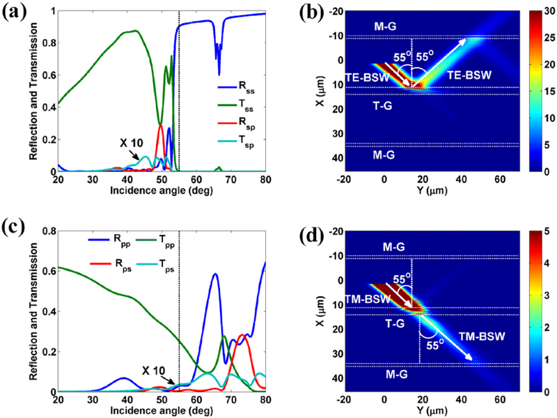
Figure 10. Polarization-sensitive beam splitter for BSWs.
(a) the reflection, transmission and mode conversion efficiencies of TE-BSW propagating across four grooves versus the incidence angle. (b) The electric field intensity distribution for TE-BSW with incidence angle 55° , which shows the total reflection of the TE-BSW by the transforming grooves (T-G). (c) The reflection, transmission and mode conversion efficiencies of TM-BSW propagating across four grooves versus the incidence angle. (d) The electric field intensity distribution for TM-BSW when it strikes at the T-G with incidence angle 55°. The white dashed lines parallel to the Y axis in (b) and (d) denote the exterior boundaries of monitoring and transforming grooves. The mode conversion efficiencies of Tsp and Tps (shown in (a) and (c)) are magnified by a factor of 10. The structural parameters of all the grooves and dielectric multilayer are the same as those used in the experiments (Fig. 6), respectively.

