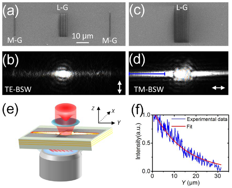
Figure 3. Launching the BSWs with grooves.
(a) SEM image of the grating for launching TE-BSW (L-G, period is 490 nm) and monitoring grooves for imaging the propagation of TE-BSW (M-G). (c) SEM image of the grating for launching TM-BSW (period is 620 nm). (b) and (d) are corresponding optical images to (a) and (c), respectively. A laser beam with wavelength at 635 nm was focused at normal incidence onto the L-G in order to launch the surface waves. The double-headed white arrows in (b and d) indicate the orientation of the incident polarization. The scale bar (10 μm) on (a) is applicable for (a-d). The grooves were inscribed on the top SiO2 layer. (e) Optical setup of the LRM. The Gaussian beam was focused onto the L-G, and then launched the BSW. The leakage radiation of the BSW is collected by the objective. (f) The blue curve line is the cross-sectional plot of (d) along the blue solid line and the red line is the corresponding exponential fitting data.

