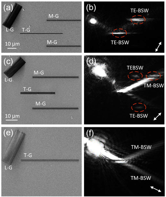
Figure 4. Reflector and beam splitter for BSWs.
(a) SEM image of the launching grating (L-G), the transforming groove (T-G) and the monitoring grooves (M-G), (b) corresponding optical image shows the total reflection of TE-BSW by the T-G. (c), (e) SEM images of the gratings and grooves working as the beam splitters for TE-BSW and TM-BSW, (d) and (f) the corresponding optical images of (c) and (e), respectively. The double-headed white arrows in (b, d and f) indicate the orientation of the incident polarization. The scale bar (10 μm) on (a) is applicable for (a-b), and the scale bar on (c) is applicable for (c-f).

