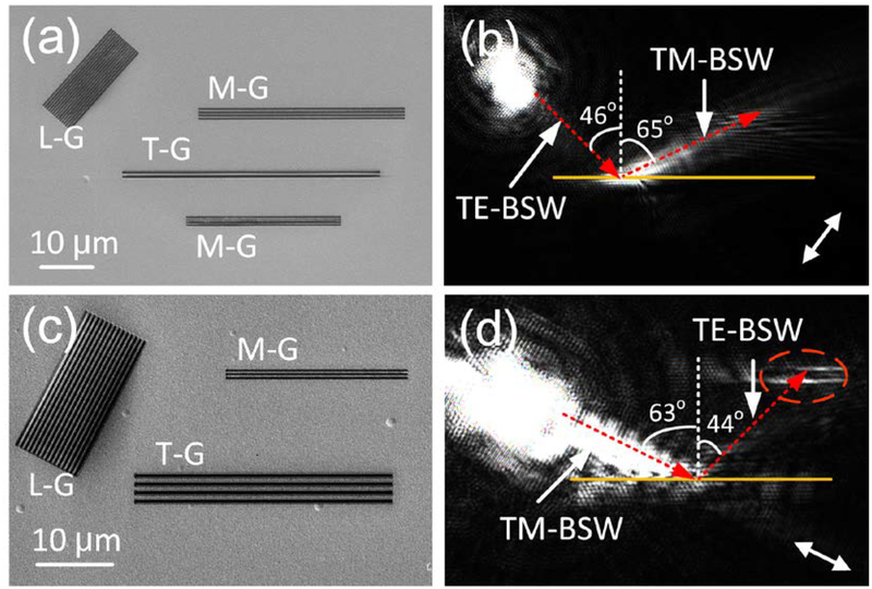
Figure 5. Polarization rotator for BSWs.
(a), (c) SEM images of the gratings and grooves working as the polarization rotator, (b) and (d) the corresponding optical images of (c) and (e), respectively. On (a) and (b), the TE-BSW was transformed into TM-BSW during the reflection by the grooves (T-G). On (c) and (d) the TM-BSW was transformed into the TE-BSW. The double-headed white arrows in (b and d) indicate the orientation of the incident polarization. The scale bar (10 μm) on (a) is applicable for (a-b), and the scale bar on (c) is applicable for (c-d).

