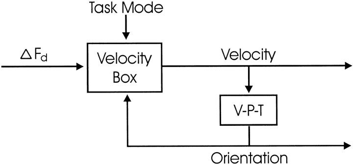
Fig. 11.
Velocity rule model of head control during gaze shifts. Desired change in 2-D head facing direction (ΔFd) is input to a velocity box, which uses information about current head orientation and task mode to compute the correct 3-D velocity command for the head. The latter is also input to a velocity-to-position transformation (V-P-T), which estimates current head orientation (Tweed and Vilis, 1987). This head orientation signal can be used to control head posture in the feedforward direction but is also fed back to the velocity box. As the movement proceeds, the velocity command shrinks toward zero, as in any negative-feedback loop. A task mode input sets the internal parameters of the velocity box, as follows. All three modes of head control (Fick, Listing, and minimum rotation) can be expressed as velocity rules. In each mode, the angular-velocity vector of the head must lie in a certain velocity plane, which is a function of the facing direction. Supposef is a unit vector (a vector of length 1) pointing in the facing direction, N is a unit vector orthogonal to the velocity plane, and i, j, andk are body-fixed unit vectors pointing forward, left and up. Then, the various head constraints we have considered take the following forms. The minimum-rotation strategy says thatN = f, i.e., the velocity vector must be orthogonal to the current facing direction; the Fick pattern says that N is obtained by rotating finto the horizontal plane, i.e., NFick= k × (f ×k), if we normalize this vector (stretch it out to make its length 1); the Helmholtz pattern says that N is f rotated into the sagittal plane, i.e.,NHelmholtz = j × (f × j) normalized; and Listing's law, as usual, is halfway between Fick and Helmholtz:NListing bisects the angle betweenNFick andNHelmholtz; equivalently,NListing bisects the angle betweenf and i, so thatNListing = f +i normalized.

