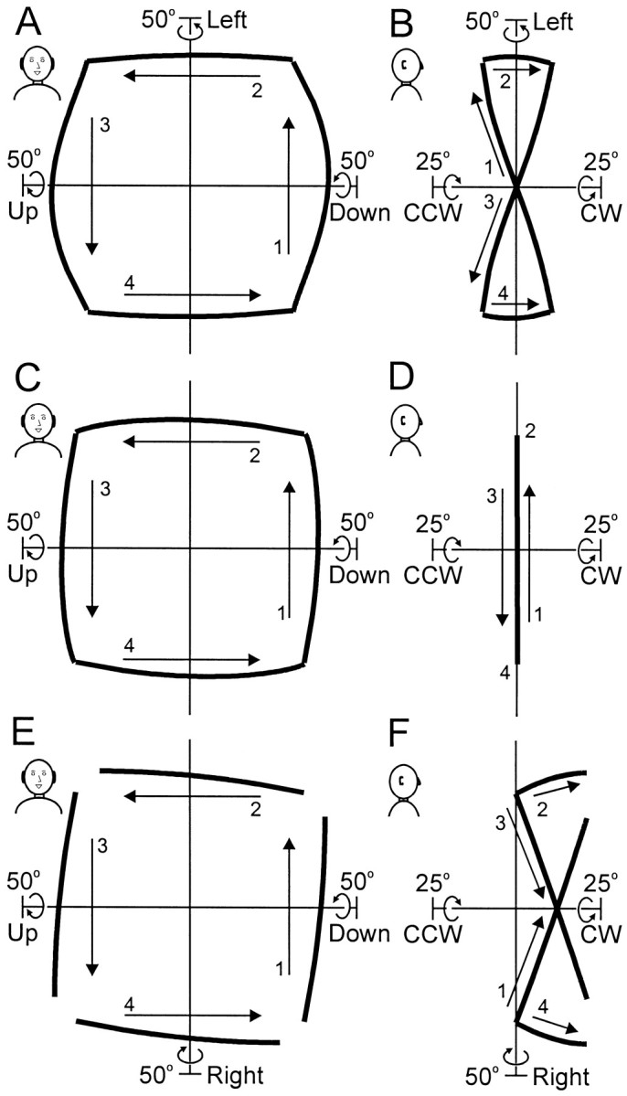
Fig. 12.

Simulations of the velocity rule model of head control. Each row plots four movements that take the facing direction clockwise between the four oblique targets of the standard array, at 48° eccentricity. Corresponding movements (labeled1–4) are viewed from the front (left column) and side (right column) perspectives.A, B, The model operates in Fick–gimbal mode, so that in the side view the head-position trajectories trace out a twisted bow-tie shape. C, D, In Listing mode, the trajectories stay in the zero torsion Listing's plane.E, F, Minimum-rotation mode puts no bounds on torsion. In these simulations, each movement starts from Listing's plane (torsional starting position is arbitrary in this mode because it would depend on the previous movement history). All four movements carry the head clockwise, so if each started where the previous one ended, clockwise torsion would accumulate. Similarly, movements in the opposite direction would cause counterclockwise accumulation, whereas randomly directed movements would cause a general increase in torsion like that observed in our gaze dissociation task (Fig. 8C). Note that the corner positions of the head differ from mode to mode in the torsional, vertical, and horizontal dimensions, although all of these positions point the facing direction at the same four oblique targets.
