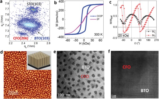
Figure 1.

Structural and microstructure of BTO:CFO VANs. a) RSM of BTO:CFO nanocomposite films on STO substrates around the STO (103) region. b) In‐plane and out‐of‐plane magnetization at 300 K. c) Angle‐dependent magnetization for longitudinal (L) and transverse (T) magnetic components under an external magnetic field of 20 kOe. d) AFM image of BTO:CFO nanocomposites. e) Plan‐view STEM image showing CFO nanopillars in BTO matrix. The dark region represents the CFO phase. The gray area shows the BTO matrix. f) Atomic‐resolution HAADF–STEM image showing the interface between BTO and CFO.
