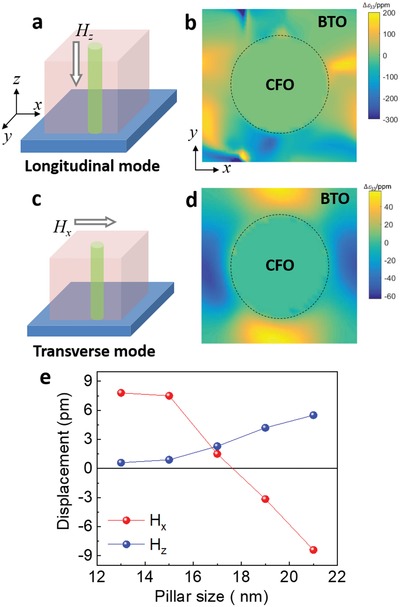
Figure 4.

a) An illustration of the longitudinal ME coupling mode with the magnetic field (Hz) parallel to the CFO nanopillars. b) The calculated distribution of the out‐of‐plane strain change, Δε 33, in the x–y plane of BTO with an external magnetic field Hz. The dashed black circle represents a CFO pillar. ppm represents 10−6. An Hz of 0.5 kOe is used in simulation. c) An illustration of the transverse ME coupling mode with the magnetic field parallel to film surface (Hx). d) The calculated Δε 33 distribution in the x–y plane of BTO with an external magnetic field Hx. An Hx of 4.4 kOe is used in simulation. The pillar size used in panels (b) and (d) is 21 nm. e) CFO nanopillar size–dependent macroscopic displacement of the BTO matrix in the presence of external magnetic fields Hx and Hz.
