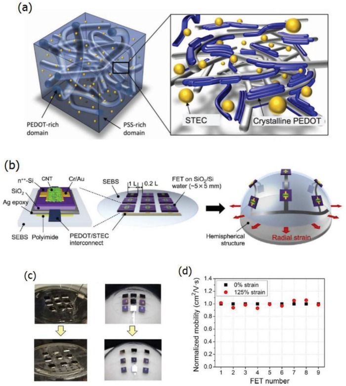
Figure 28.

a) Schematic diagram of the typical PEDOT:PSS film with stretchable and conductive ionic additive enhancers (STEC). b) Schematic representation of a rigid‐island FET array with stretchable PEDOT:PSS interconnects. c) Photographs of the FET arrays that are strained in all directions on flat surfaces and spherical objects, respectively. d) Normalized mobility of individual devices when the array is stretched to 125% strains. Reproduced with permission.109 Copyright 2017, American Association for the Advancement of Science.
