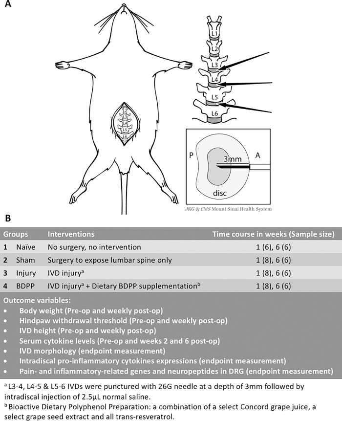
Fig 1. IVD injury and study design.
(A) Schematic diagram illustrates the surgical procedure for inducing IVD injury. ‘P’ and ‘A’ represents posterior side and anterior side of IVD, respectively. After exposing the lumbar spine, the L3-4, L4-5 and L5-6 IVDs were punctured anteriorly along the midline to a depth of 3mm followed by intradiscal injection of normal saline. Image created from Mount Sinai Health System. Used with permission. (B) Experimental design of current study.

