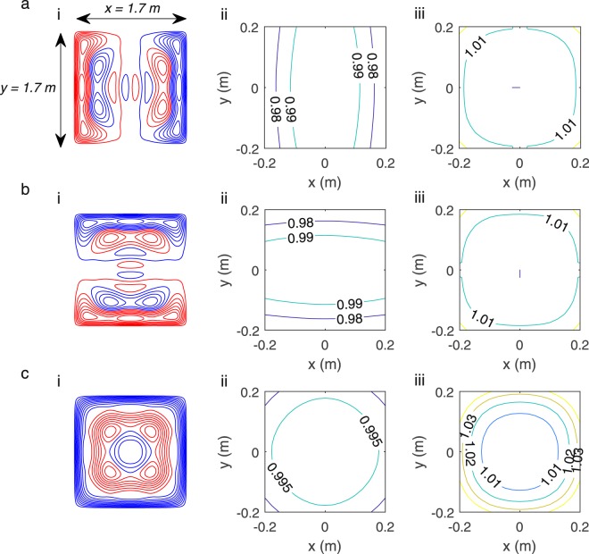
Figure 4.
Final coil designs and simulated fields. Wire paths (i) and field (ii) or field gradient contours (iii) for the: (a) Bx and Gx coil, (b) By and Gy coil and (c) Bz and Gz coil, respectively. Red and blue denote wires with opposite senses of current flow. The contours of the field or field gradient in the plane at z = 0 m, for |x|, |y| < 0.2 m (z = 0.025 m, for |x|, |y| < 0.2 m for Gz) are shown. The field values are normalised to the field at the centre of the plane or a value slightly off-centre when the central field is zero.

