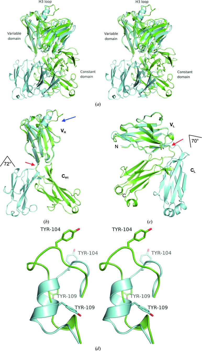
Figure 1.
(a) Superposition of the EV1007-Fab (green) and MB007 (cyan) structures. The structures were superposed at the variable domain of the heavy chain (VH). (b, c) Rotations at the hinges (indicated by red arrows) between VH and CH1 superposed at the VH region (b) or VL and CL superposed at the VL region (c) of EV1007-Fab (green) and MB007 (cyan). As indicated in the figure, the angle of rotation is 72° and 70° for the heavy and light chain, respectively. The H3 loop region is shown by a blue arrow. (d) Stereo image of the superposed H3 loops of MB007 and EV1007-Fab. The side chains of Tyr104 and Tyr109 are shown as stick models. For clarity, the rest of the protein is not shown. The top part of the figure (the direction of the side chain of Tyr104 in both structures) is the part where the protein is exposed to the solvent, and the bottom part of the figure (the direction of the side chain of Tyr109 in the MB007 structure) is where the rest of the protein is located.

