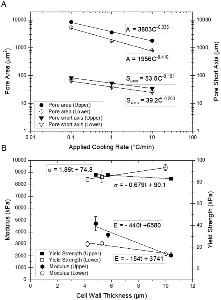
Figure 13.
(A) Pore area and short axis (mean ± S.E.) plotted versus applied cooling rate for the upper and lower regions of longitudinally frozen scaffolds; (B) yield strength and modulus (mean ± S.E.) plotted versus cell wall thickness for the scaffolds at the three different applied cooling rates.

