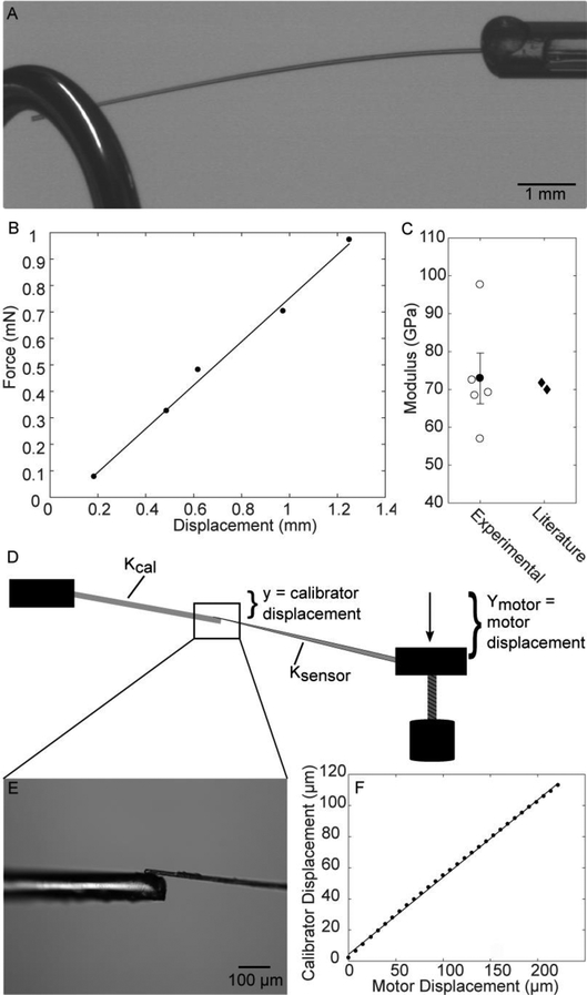
Figure 3.
Microneedle calibration method. A) A weight is hung from the optical fiber calibration standard. B) The displacement of the optical fiber and the force due to the weights are plotted to find the optical fiber stiffness. C) The stiffness is used to calculate the fiber modulus and compare to literature values. Open circles represent individual fiber modulus values, the filled circle is the mean. Error bars show standard error. D-E) Micropipette calibration setup. The displacement of the optical fiber by the microneedle is tracked. F) The linear regression of the calibration fiber displacement and the motor displacement is used to calculate the stiffness of the microneedle.

