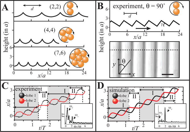
Figure 3.
μWheel translation on topographic surfaces. (A) The calculated commensurate “roads” for μwheels of size n = 2, 4, and 7 where optimal spacings d are 6.3a, 3.8a, and 3.1a. (B) Experimental geometry (measured by AFM along θ = 90°) with minimum spacing of d = 4.4a and blaze angle γ = 26°; spacing can be readily increased by lowering translation angle θ. Maximum height = 1.7a and arrow indicates blaze direction. Scale bar: 4 μm. (C) Experimental measurement of displacement of the centers of mass of two dimer lobes with time rolling along θ ~ 90° against the blaze direction. Mode I: rotation with slip; Mode II: non-slip flipping. (insets: Fourier transform of the instantaneous velocity). (D) Calculated displacement of the centers of mass of two lobes of a dimer rolling along a textured surface with trapezoidal bumps (Fig. S3B) Insets show the Fourier transforms of the instantaneous velocity.

