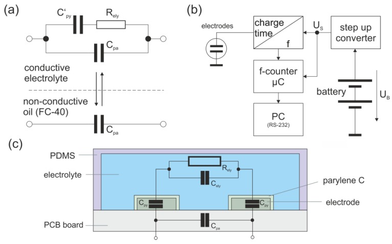
Figure 3.
Equivalent circuit diagram and setup of the conductivity sensor. (a) Simplified equivalent circuit of the sensor setup. Alternating contact with conductive and nonconductive liquids changes the electrical properties of the electrodes. Cpa includes all parasitic capacities, such as stray capacitance of the printed circuit board (PCB), input capacitance of the electronic system, etc. C’py is the capacity of the insulating parylene C layer above the electrodes, and Rely represents the ohmic resistance due to the limited conductibility of the electrolyte. (b) Block diagram of the electronic system used for sensing of the conductivity. A step-up converter upregulates the battery voltage UB to the supply voltage US required for the microprocessor. The charge and discharge times of the capacitor are monitored and converted into a rectangular signal with corresponding frequency. The frequency is read out via a microcontroller and communicated to a PC via a RS-232-interface. (c) Scheme of the setup of the microfluidic channel with the sensing electrodes.

