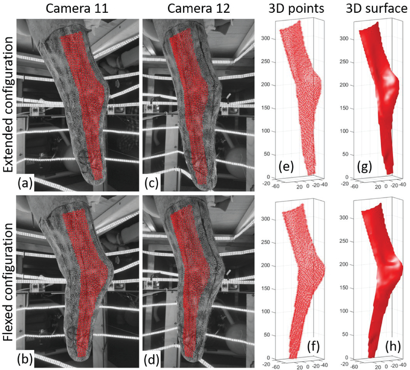
Fig. 3.
Workflow of residual limb surface reconstruction using 3D-DIC. Portions of the speckled residual limb imaged by camera 11 (a,b) and camera 12 (c,d) are shown in two configurations: extended knee (top row) and flexed knee (bottom row). The points correlated between all four images (a-d) are plotted with red crosses on top of the images. The resultant 3D point clouds (e,f) and triangular meshes (g,h) are plotted for the two configurations. All the axes in plots (e-h) are in millimeters.

