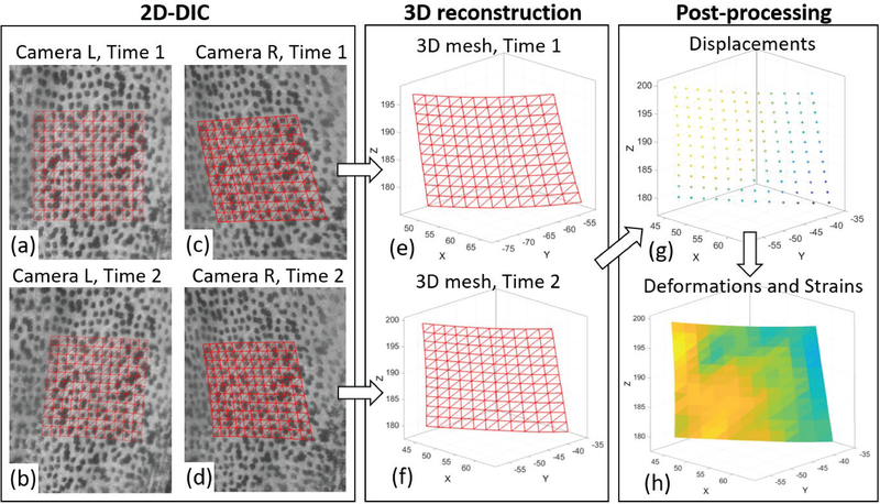
Fig. 4.
Schematic workflow of 3D-DIC for one stereo-pair. Portions of the speckled surface imaged by the left (L) camera (a,b) and right (R) camera (c,d) are shown in two time steps corresponding to the reference configuration (Time 1) and a deformed configuration (Time 2). The reference square point grid is defined on the reference image (a), and the points are then identified on the images (b-d) using 2D-DIC. In addition, a triangular mesh is defined on the reference image by sub-dividing the squares, and the mesh connectivity is preserved in all the images. Then, the image points from each stereo pair are reconstructed in a 3D coordinate system using stereo triangulation (e,f). The displacements from Time 1 to Time 2 are calculated on the measurement points (g), and consequently the 3D deformations and strains are calculated on the triangular elements (h).

