Fig. 5.
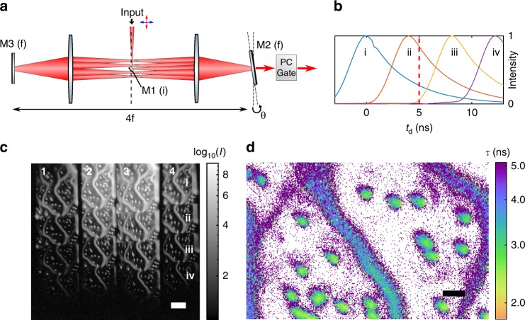
Multi-frame nanosecond imaging with a cavity time-to-space converter. a Externally gated, tilted mirror 4f re-imaging cavity. Image input is on small in-coupling mirror M1 in an image plane (i). M2 is tilted at a diffraction plane (f), spatially offsetting the images at the M1 plane each pass. Each round trip, images are passively out-coupled through partially transmissive mirror M2. b Normalized image intensities for four output images from the cavity showing a 4 ns round trip delay. c Cavity output on camera (CMOS) shows 4 x 4 images output from the PC analyzer. The columns are numbered 1-4 in analogy to Fig. 1, and the rows (i–iv) give the outputs from the first four cavity round trips (scale bar 50 μm). The sample is a mixture of drop-cast nile red 2 μm beads (~3.1 ns) and orange 0.1 μm beads (4.9 ns) that form the diffuse filaments. d The ratio of output frames (row i, column 4) and (row ii, column 4) in the gated channel at td = 5 ns (red line in (b)) is used for single-frame FLIM as described in the text. The two labels are readily differentiated (scale bar 10 μm)

