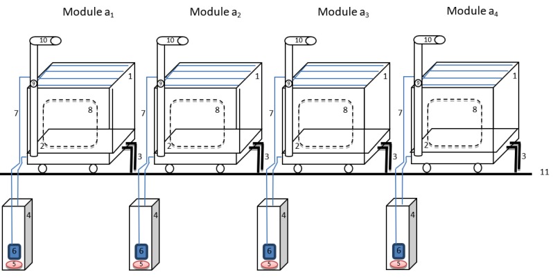
Figure A1.
Sketch for the composting facility—4 modules [68]. 1—tank with capacity of 1 m3 for compost components; 2—rack for compost; 3—tank heating system for composting; 4—tank for the collection and recirculation the water excess, built underground; 5—heating elements for wetting water (purine); 6—water/purine recirculation pump; 7—recirculation pipes for wetting water/purine; 8—compost discharge door; 9—air flow control valve for aerobic composting; 10—air inlet pipe to aerobic composting from the compressor; 11—ground level.

