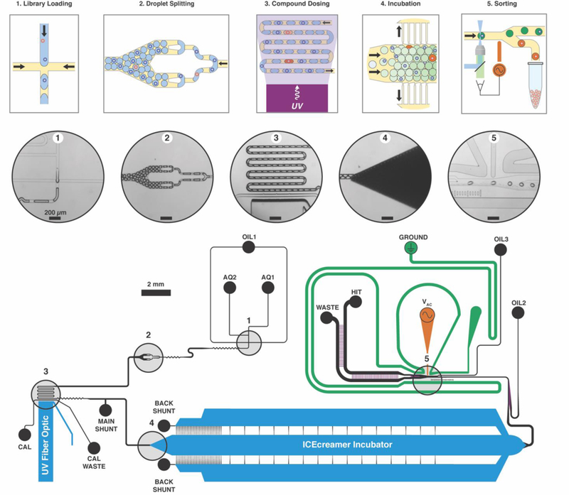
Figure 1. Integrated microfluidic screening architecture.

Library beads enter the circuit together with ATX activity-based fluorogenic substrate (AQ1) and mix with enzyme (AQ2) immediately upstream of the water-in-oil (OIL1) flow-focusing junction (1) where droplets form (15 Hz). Flow continues toward the droplet splitter (2), which splits each droplet in half twice (60 Hz). Compound is released from beads into the ATX activity assay droplets as they traverse a serpentine photochemical reactor illuminated with a 365-nm waveguide-coupled LED (3). Oil drains from the droplet flow, packing droplets in the ICEcreamer (4) for assay incubation. At the incubator exit, two oil flows space (OIL2) and focus (OIL3) the droplet stream for analysis. Laser-induced fluorescence assay detection occurs upstream of the droplet sorting junction (5). Hit droplets are statistically significantly less fluorescent than the overall instantaneous droplet population, and trigger a high-voltage AC pulse to the working electrode (VAC) that electrokinetically forces the hit droplet toward the electrode and into the hit collection flow. Channel heights depicted in purple and blue are 30 μm and 250 μm, respectively. All other channel heights are 50 μm.
