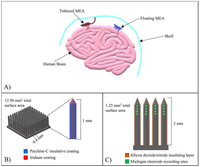
Figure 2:
MEA configuration examples. (A) Schematic demonstrating the difference between tethered and floating MEAs. Tethered MEAs, following implantation into the brain, are permanently attached to the skull to restrict movement, whereas floating MEAs are free to move around with the brain. (B) Schematic detailing the Utah MEA configuration. Grids of silicon electrodes 1 mm long, with 0.4 mm spacing and surface area of 12.96 mm2, coated with Parylene-C and iridium. (C) Schematic detailing the Michigan MEA configuration. A quad shank arrangement with 16 recording sites, with each shank coated with silicon dioxide/nitride and measuring 3 mm in length (total surface area of 1.25 mm2).

