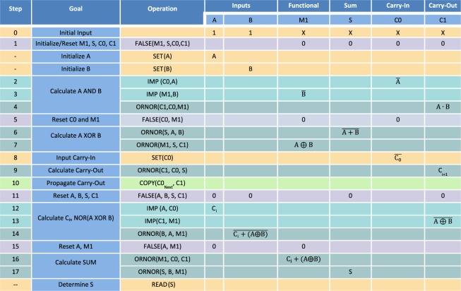
Figure 3.
Clocking scheme for a full adder. Each line corresponds to a step in the full adder, with the exception of simulation requirements for loading and transferring data (marked by–). Each step provides the operation that is performed, including the memristive switches that are part of the computation. The result of the operation is shown for each memristive switch, and if there is no value in a cell, it is assumed that the memristive switch maintains its previous state. SET operations are yellow, FALSE operations are violet, COPY operations are light green, IMP operations are green and ORNOR operations are dark green.

