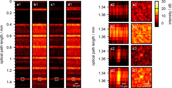
Figure 6.
Lateral sample scan with shaped wavefronts applied. (a1) B-scan taken with flat wavefront applied to both beams. (a2) B-scan close-up centered at the target scan position which was chosen for wavefront optimization. (a3) En-Face scan at the target depth () for wavefront optimization. (b1–b3) Same as (a1–a3) with wavefront optimized at the reference beam (Fig. 5d). (c1–c3) Same as (a1–a3) with wavefront optimized at the sample beam (Fig. 5c). (d1–d3) Same as (a1–a3) with both wavefronts applied to the respective beams simultaneously.

