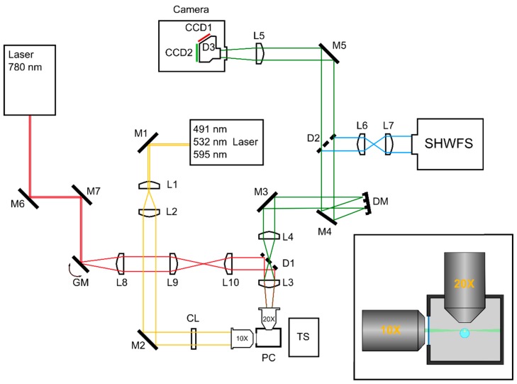
Figure 1.
(left) Schematic image of the WAOSPIM system. L1–10: Lenses; M1–7: Mirrors; D1–3: Dichroic beamsplitters; CL: Cylindrical lens; DM: Deformable mirror; SHWFS: Shack–Hartmann wavefront sensor; GM: Pair of galvanic mirrors; PC: Physiological chamber; TS: Translation stage. (right) Top-down view of the sample mounting scheme. The sample is placed inside an agarose cylinder that hangs from a movable stage. The physiological chamber is filled with an aqueous solution.

