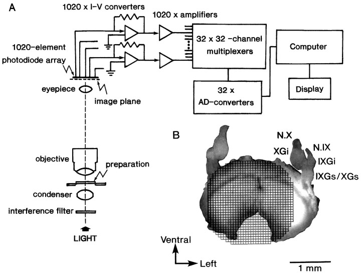
Fig. 1.
Schematic drawing of the simultaneous 1020-site optical recording system. A, The preparation chamber is mounted on the stage of an Olympus Vanox microscope (type AHB-L-1). Bright-field illumination is provided by a 300 W tungsten–halogen lamp (type JC-24V/300W, Kondo-Philips) driven by a stable DC power supply. Incident light is collimated, passed through a 703 ± 15 nm interference filter (Asahi Spectra), and focused on the preparation by means of a bright-field condenser with an NA matched to that of the microscope objective (S plan Apo, 10×, 0.4 NA). The objective and photographic eyepieces project a magnified real image of the preparation onto a 34 × 34-element silicon photodiode array. The outputs from 1020 elements are fed into individual current-to-voltage converters followed by individual amplifiers. The amplified outputs are then fed into 32 sets of 32-channel analog multiplexers via individual RC low-pass filters. Each output of the 32 analog-to-digital conversion systems is digitally multiplexed and is sent to a specially designed interface in the computer system (LSI 11/73 system, Digital Equipment) using a fiber-optic transmission system. The time resolution of this system is 1024 samples/sec for each element. B, Example of the relative positions of the image of the brainstem slice preparation dissected from a 16-d-old rat embryo and the 1020-element photodiode array grids. N.IX, Glossopharyngeal nerve;N.X, vagus nerve; IXGs, superior glossopharyngeal ganglion; IXGi, inferior glossopharyngeal ganglion; XGs, superior vagal ganglion;XGi, inferior vagal ganglion.

