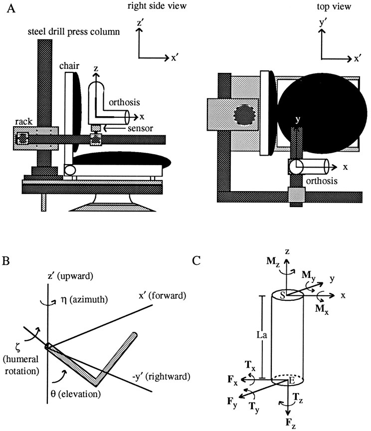
Fig. 1.
Experimental apparatus (A), angles defining arm posture (B), and a free-body diagram of the forces and torques exerted on the upper arm (C).A, A six-degree-of-freedom force–torque sensor was rigidly coupled to an upper extremity orthosis at one end and a stereotaxic frame at the other. Two coordinate frames are illustrated: an x, y, z, frame that was fixed to the arm/sensor, and an x′, y′,z′ frame (inset) that was fixed in space. In this posture, the axes of the two frames were parallel. Thez- and x-axes were aligned with the long axes of the upper arm and forearm segments of the orthosis, respectively; the y-axis was orthogonal to the plane containing these two axes. B, Three angles were used to define upper arm posture: η, a rotation about the verticalz′-axis; θ, a rotation in a vertical plane passing through the upper arm (measured relative to the verticalz′-axis), and ζ, a rotation about the long axis of the humerus. C, A cylinder representing the upper arm is depicted along with the forces (Fx,Fy, Fz) and torques (Tx, Ty,Tz) recorded at the transducer and the corresponding torques at the shoulder (Mx,My, Mz). The shoulder, elbow, and length of the upper arm are labeledS, E, and La, respectively.

