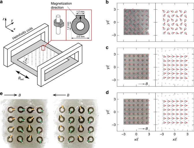
Fig. 2.
The array of rotors in static magnetic field and weak oscillating magnetic field. a Schematic of the experimental set-up, consisting of a Helmholtz coil system, with the 3D printed pin system placed in the centre. The inset shows a rotor mounted on a pin and indicates its dimensions. b–d Snapshots of orientational configuration under a static field with b , c 0.2 and d 10.0. The external magnetic field is imposed to right. Left column shows result from the experiment while right shows the simulation. Red arrows describe the magnetic moment direction, while grey arrows in c, d denotes magnetic field direction created by the rotors. e Experimental observation of the stripe swinging pattern for a 44 rotor array under and . The arrows depict the direction of the magnetic moments, and the two frames show the moment when the external magnetic field reached and , respectively

