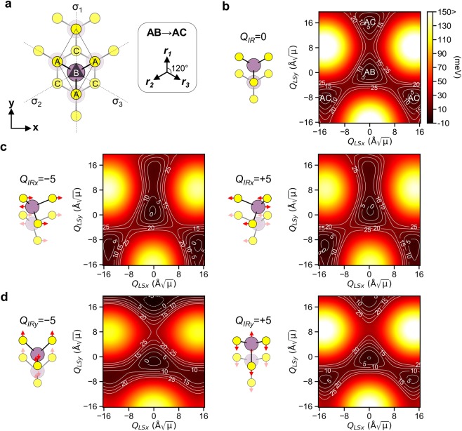
Figure 2.
(a) Top view of the AB stacked 3R MoS2 showing the C3v symmetry. In the AB stacking, the S atoms in the upper layer are on the top of the Mo atoms in the lower layer (bottom layer is depicted as dimmed). The x- and y- axis corresponds to the zigzag and armchair axis of MoS2, respectively. The AB stacking changes to the AC stacking under the deformation induced by the positive amplitude of QLS along the three equivalent directions r1, r2 and r3. (b) Potential energy surface V(QIR, QLSx, QLSy) on the (QLSx, QLSy) coordinates for QIR = 0 Å (μ is atomic mass unit). The AB stacking corresponds to the origin (0, 0). Polarization-dependent modulation of the potential energy landscape at (c) QIRx = ±5 Å and (d) QIRy = ±5 Å via anharmonic coupling.

