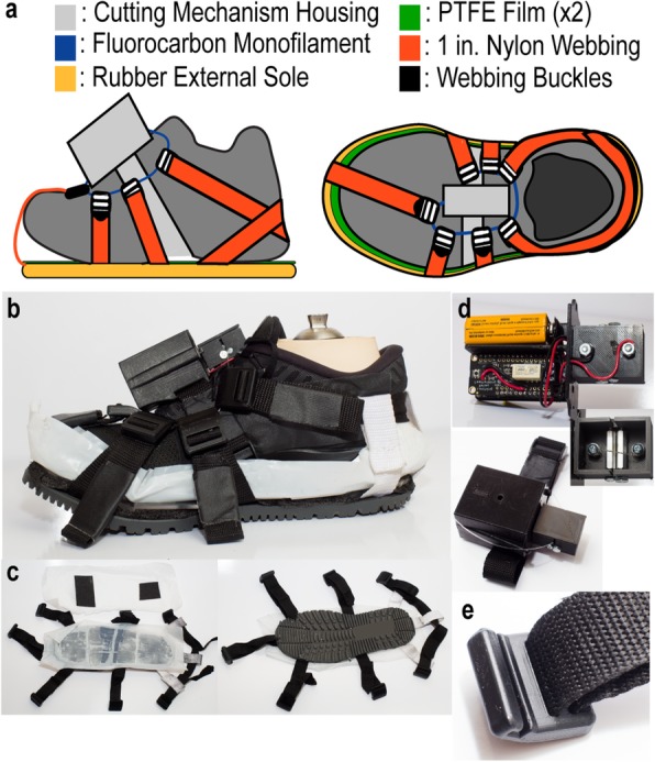
Fig. 1.

a Color-coded diagram of WASP, individually highlighting the components. b The entire WASP assembly fitted to a shod prosthetic foot. c Superior and inferior views of the WASP outsole with PTFE sheets and straps. d The trigger mechanism, detailing the internal electronics and the nichrome interface. e An example of the custom 3D printed buckles used to connect the two components via the fluorocarbon filament
