. 2019 Oct 7;8:e47405. doi: 10.7554/eLife.47405

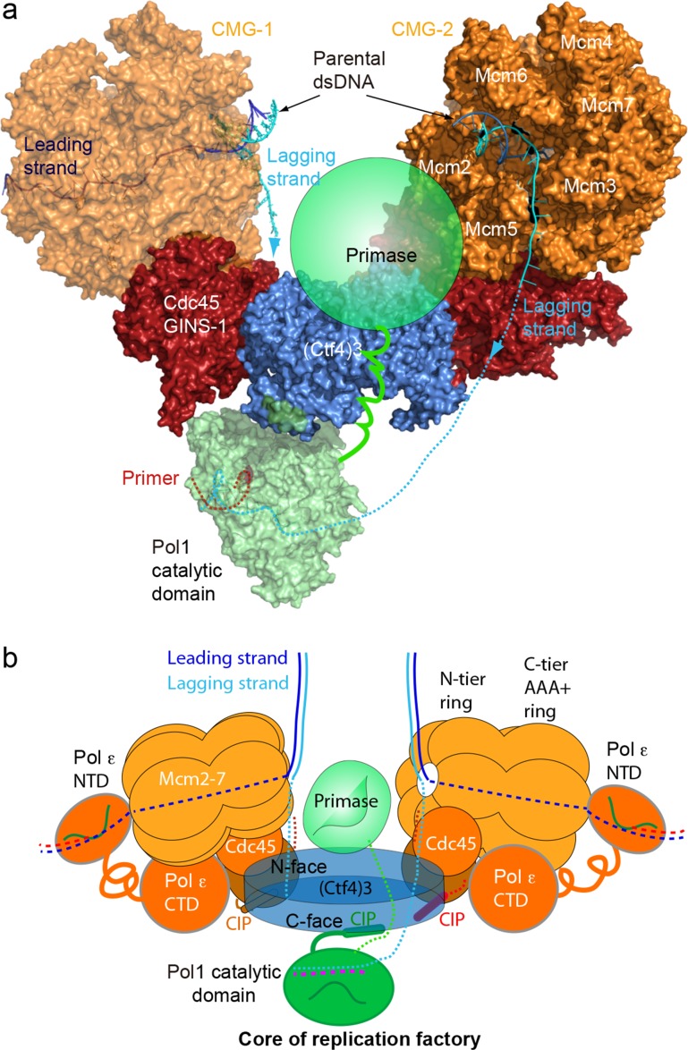
Figure 8. A model for the coupled sister replisomes.

(a) A composite atomic model of one Pol α-primase and two CMG helicases organized in a core factory with a Ctf4 trimer. The model is derived by aligning Ctf43 shared between the Ctf43–CMG dimer model and the model of Ctf43–Pol α NTD. The DNA structure is based on the structure of CMG–forked DNA (PDB 5U8S), but the lagging strand outside the CMG channel is modeled. The possible location of the primase module of Pol α-primase is indicated by a green ellipse. (b) A sketch illustrating the leading strand Pol ε at the C-tier face of the CMG helicase and the primase reaches atop the N-face of Ctf43, potentially capable of priming both lagging strands. See text for details. See also Figure 8—figure supplements 1 and 2, and Video 3. Figure Supplements and their legends.

Figure 8.

Figure 8—figure supplement 1. The Pol1 and primase lobes of Pol α-primase have a 70° range of motion.
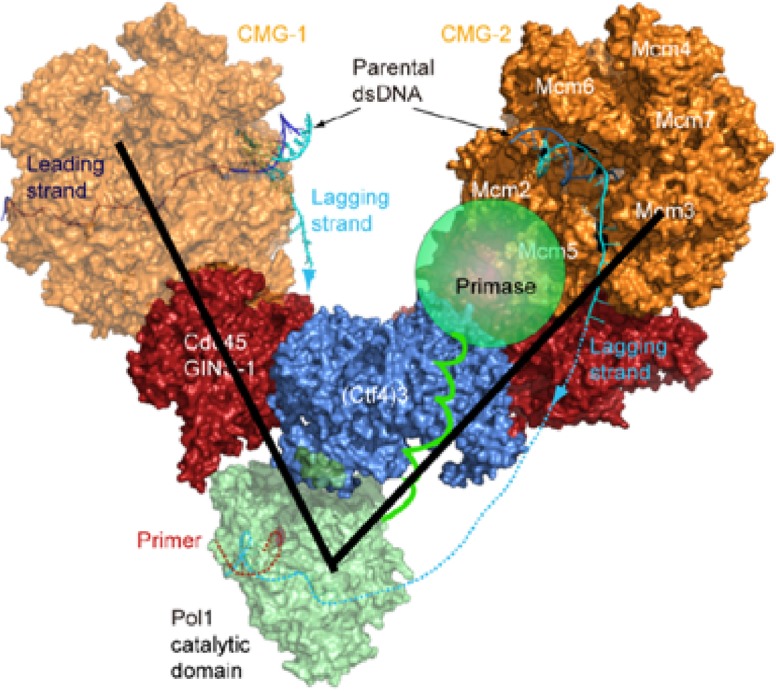
Figure 8—figure supplement 1.

The primase lobe of Pol α-primase is shown as a semi-transparent sphere connected to Pol1 by a flexible linker. Assuming the primase lobe extends past the Ctf43 disk and resides near the CMGs, the black lines indicate a 70° angle to approximate the previously documented range of motion between the Pol and primase lobes (Núñez-Ramírez et al., 2011).
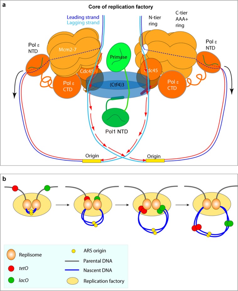
Figure 8—figure supplement 2. Comparison of the proposed sister replisome core factory to conclusion of super-resolution imagine of marked DNA in cells.

Figure 8—figure supplement 2.

(a) Cartoon of the structural model of a core replicon factory from the current report, along with DNA produced from one bidirectional origin. The black arrows indicate the direction of duplicated leading strand DNA propelled from the leading strand Pol ε in the complex, and the red arrows correspond to the direction of lagging strand synthesis during Okazaki fragment extension. Panel (b) is adapted from Figure 1a in Natsume and Tanaka (2010).