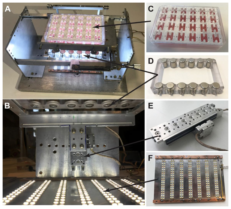
Figure 2. Afterload device and its individual components.
(A) Top view of the afterload device in its assembled form. (B) Close-up front view of the device. (C) The 24-well plate containing 6 racks of EHTs sits on top of an aluminum plate holder. (D) The magnet plate containing two rows of cylindrical permanent magnets is horizontally mounted to the (E) piezoelectric stage below the EHTs. (F) A plate with strips of LEDs sits at the base of the device to illuminate the tissues for imaging.

