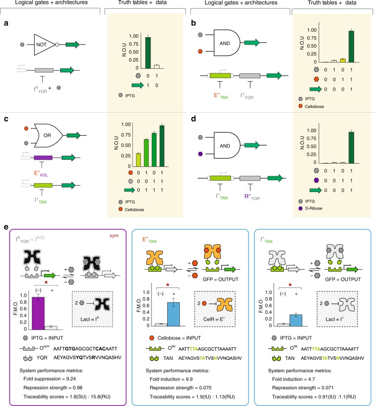
Fig. 5.
Biological logical gates NOT, AND, and OR. a An engineered LacI suppressor (antilac) represents a unary NOT gate, the output is OFF when IPTG is present. Y-axis is given as normalized output units or N.O.U. This is calculated by taking GFP fluorescence (485ex., 510em.) normalized to OD600, which is further normalized to the maximum output for each experiment. Each value corresponds to the mean of n = 6 biological replicates and error bars indicate the 95% confidence interval (95% CI), or approximately two times the standard error of the mean (s.e.m.). b A biological AND gate achieved via the SERI architecture utilizing two X+ADR with orthogonal DNA recognition and ligand response. Values correspond to n = 18 biological replicates. c Biological OR function achieved through PARA architecture where each copy of GFP is controlled by a distinct X+ADR. Values correspond to n = 12 biological replicates. d Another iteration of a biological AND gate utilizing distinct input signals, via two non-natural transcription factors. Values correspond to n = 18 biological replicates. e Transcription factor operator pairs utilized in logic gates (a–d), along with their performance characteristics. For performance cards, values represent the mean of n = 12 biological replicates. Data in the cards have been normalized relative to the maximum value of 20,000 GFP/OD600 a.u. Note: the IA suppressor used in the representative NOT gate is IA(5)YQR, created in our previous report (Rondon and Wilson)53. Source data are provided as a Source Data file, and individual data points overlaid as dot plots can be found in Supplementary Fig. 7

