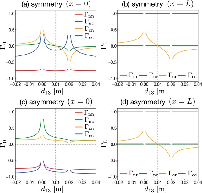
Figure 4.
Matrix elements of Γ0 (x = 0) and ΓL (x = L) as functions of the distance d13 between lines 1 − 1′ and 3 − 3′. Two different circuits equivalent to symmetrical (Fig. 3) and asymmetrical (Fig. 1) circuits are used. The distance between lines 1 − 1′ and 2 − 2′ is d12 = 0.02 m in each circuit. The length and radius of the three lines are L = 2 m and 0.5 mm, respectively. The values of the resistances are R12 = 50 Ω, R23 = 5 Ω, R13 = R23 = 300 Ω, and R12′ = 349.715 Ω, which is equivalent to the characteristic impedance between lines 1 − 1′ and 2 − 2′(=Znn).

