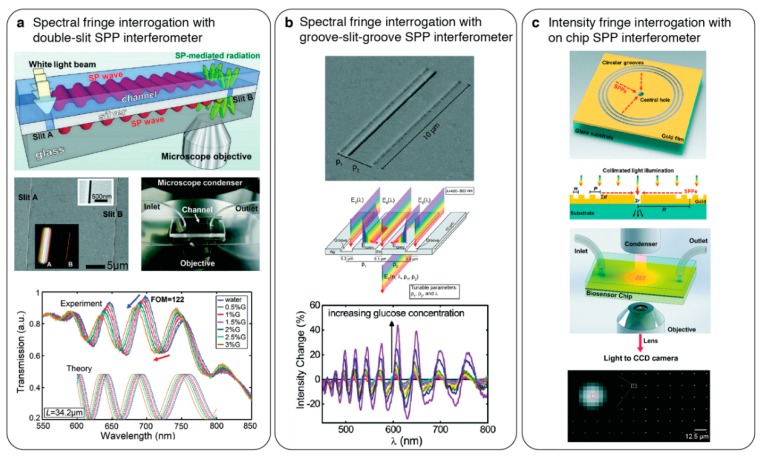
Figure 10.
On-chip surface plasmon polariton interferometry. (a) (top) Schematic showing an on-chip Mach–Zehnder interferometry configuration. Nanoslit coupled propagating plasmons on the sensing channel and reference substrate interfere at the second slit where an objective collects the scattered light and fringe analysis is performed by a spectrometer. (middle) SEM showing the nanoslits and photograph of integrated microfluidic chip. (bottom) Spectra showing fringe shift as the refractive index of the sensing media increase. Adapted with permission from [98] Copyright 2011 American Chemical Society; (b) (top) SEM of a groove-slit-groove planar plasmonic interferometer where the groove distances to the slit are uneven. (middle) Schematic showing the working principle of plasmonic interferometer. Diffractively coupled surface plasmons at the grooves counter-propagate and interfere with the free-space propagating light at the slit where the transmitted light carries the sensing information. (bottom) Plot shows intensity changes in the fringe shifts as the top media refractive index increases. Adapted with permission from [99] Copyright 2012 American Chemical Society; (c) (top) intensity interrogating surface plasmon interferometry implemented by circular grooves and central hole geometry. (middle) Schematic showing collinear optical path with a monochromatic illumination probing the fringe shifts. (bottom) Bright-field image recorded by a CCD camera showing a large array of interferometers. Reproduced from [100,101] with permissions from The Royal Society of Chemistry.

