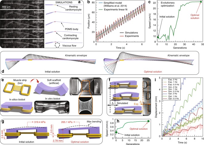
Fig. 2.
Bio-hybrid robotic design. a One-to-one comparison of the robot with experimental photographs23 at different stages within one swimming cycle. b Axial position of the robot’s center monitored over more than 20 cycles compared with experimental data. c Optimization course: Convergence to optimal solution is observed after 48 generations. Optimization was constrained with head length within , head radius within , tail radius within and cell location at any point along the tail. The bot longitudinal dimension is fixed at , so that the tail length can be inferred from the head length. The parameter ranges are determined to account for actual manufacturability. d Visualization of both the original and the optimal designs showing configurations at rest and midline kinematic envelopes over one period. Original swimmer details: substrate is modeled with 424--long head and 1503--long tail with radii and respectively. Density , Young’s modulus , bending stiffness , mass are set according to Williams et al.23. The contractile cell is modeled with radius and length . The cell is set to produce a contracting force with beating frequency 23. The fluid has dynamic viscosity . Optimized swimmer details: substrate has length and radius of and , respectively. The contractile cell is attached away from the head and the tail is thick. e Overall design of the walker with yellow elements representing muscle rings and purple elements representing the skeleton. Experimental images adapted from21. f Simulations versus experiments: Bot displacement over 2 seconds for the actuation frequency 1 Hz. g Visualization of initial and optimized design of the walker. h Optimization course converges after 25 generations. Optimization was constrained with skeleton's Young's modulus [250–350] kPa, length of the shorter pillar [2.4–3.4] mm and location of muscle strip [0.5–3] mm (distance from ground), all of which are chosen according to manufacturability constraints. i Dynamic behavior of simulated (solid lines) and experimental (markers with error bars) walker with muscle contraction at different frequencies, and comparison of walking performance between initial (solid lines) and further optimized design (dashed lines)

