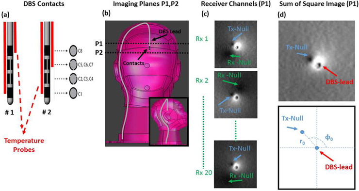
Figure 1.
A)Diagram of DBS electrode contacts and the position of temperature probes are shown.
B)Two imaging planes used to image the DBS in the pre–scan are shown.
C)Images acquired by 3 of 20 individual receiver channels are shown. Note that the individual images show two null-locations due to interaction of the lead with the receiver and the transmitter coils.
D) Sum of Square image (reconstructed from individual receiver channels) shows the location of a single Tx-Null whose location strictly depends on the RF induced current and the transmit field of the body coil.

