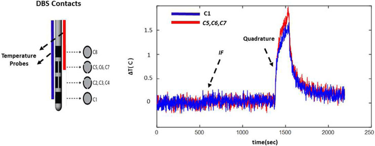
Figure 13.
The temperature increase at the contacts C1 and C5-C7 (Configuration 2, Figure 1 panel a.) is shown. Similar to configuration 1, the temperature at both contact points were mitigated simultaneously as a result of using the implant friendly excitation.

