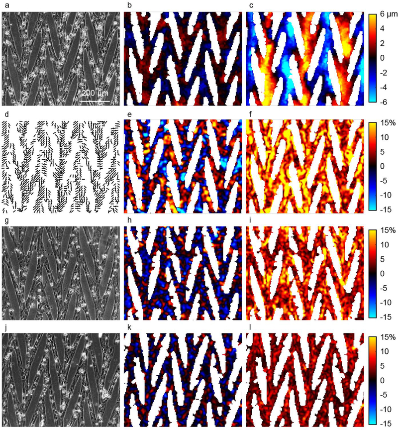
Fig. 7.
Displacements and strains of a CM array computed with DIC. (a,g,j) Bright field images of CMs micropatterned into a chevron pattern. (b, c) Displacements in horizontal (b) and vertical (c) directions, uh and uv. Red (positive) indicates rightward and upward. Color scale bars for panels (b) and (c) are the same. (d) Lines show orientation of second principal strain, indicating the primary axis of contraction. Lines are shown only in locations for which the magnitude of second principal strain is greater than 2%. (e,h,k) Sum of principal strains, e1 + e2, gives a measure of relative change in area at each location within the CM array. (f,i,l) Difference of principal strains, e1 − e2, quantifies a relative magnitude of shape change at each location within the CM array. (a-f) CMs on a compliant substrate with Young’s modulus of 5 kPa, in comparison to substrates of 10kPa (g-h) and 50 kPa (j-l). Color scale bars for panels (e-f, h-i, and k-l) are the same.

