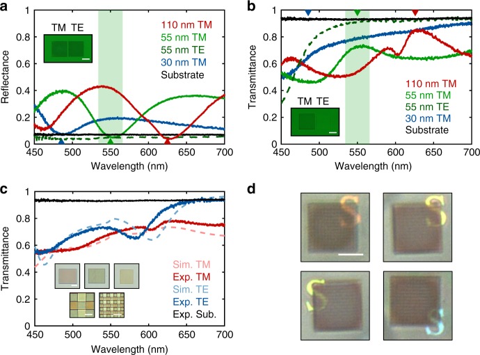
Fig. 2.
Transparency of fabricated NW array pixels. a Reflectance and b transmittance as a function of wavelength for three different NW array pixels designed for red (w = 110 nm, p = 310 nm), green (w = 55 nm, p = 280 nm), and blue (w = 30 nm, p = 230 nm) light for both polarizations. The inverted triangles indicate the wavelengths at which the NW pixels show zero reflectance in the simulations. The reflectance and transmittance of the substrate (black) is also included for reference and the reflection from the back surface of the sapphire substrate is removed in post data-processing. Insets: a Reflection and b transmission optical images for “green” pixels for two orthogonal polarizations. The incident light is polarized in the vertical direction and the NWs are aligned in the vertical direction for the left pixel and in the horizontal direction for the right pixel, respectively. A green color filter was used. Scale bar: 25 μm. c Overall white-balanced transmittance of three different NW array pixels as a function of wavelength for both polarizations. Insets: Transmission optical images of 25 μm size (top), 5 μm size (bottom left), and 2 μm size (bottom right) NW array pixels under TM-polarized illumination. Scale bar: 10 μm (top) and 5 μm (bottom). d Optical reflection images of multiplexed 5-μm-size NW array pixels under unpolarized white-light top illumination. Different colored letters “S” are placed under the pixel array. Scale bar: 25 μm

