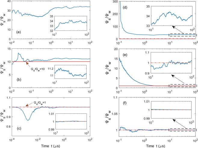
Figure 8.
Phase synchronization for setups A2 [(a–c)] and B2 [(d–f)]: Evolutions of the ratios for the phases of the strongly [] and weakly [] driven cavity modes. In setup A2, we fix other parameters and change the coupling strengths to be: (a) , (b) , and (c) , where and . In setup B2, the spring coefficients are: (d) , (e) , and (f) , while . The red line in each panel denotes the forecasting value . Here, for setup A2 and for setup B2. All the other parameters are the same as in Fig. 7.

