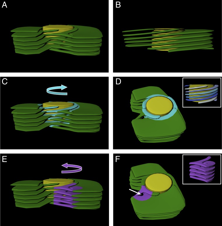
Fig. 7.
Idealized 3D model of the granum–stroma assembly. An idealized model was constructed with one left-handed helical connector per granum for visualization of all features of the granum–stroma assembly. The average number of helical connectors per granum found in the networks that were analyzed was about 4, further relieving elastic deformations at different points around the grana. In all panels, granum thylakoids are shown in yellow and the stroma lamellar sheets are shown in green. Right-handed helices (C and D) and the left-handed helical connector (E and F) are highlighted in light blue and purple, respectively, and their handedness is demonstrated with curved arrows in C and E. (D, Inset) Side view of the right-handed helices with blue hue colors highlighting the distinct helices around the granum. (A, B, C, and E) Side view of the assembly, with A, C, and E presenting a front view showing the connections between the helices, helical junction, and the sheets and B presenting a back view, allowing for better visualization of the winding of the stroma lamellae around the granum body connecting directly to sheets. (D and F) Top-angle view showing the channel formed by the left-handed helical connector (white arrow in F). (F, Inset) Side view of the isolated left-handed helical connector. The slit-like apertures that connect between the right-handed stroma lamellar helices and the grana thylakoids are not shown.

