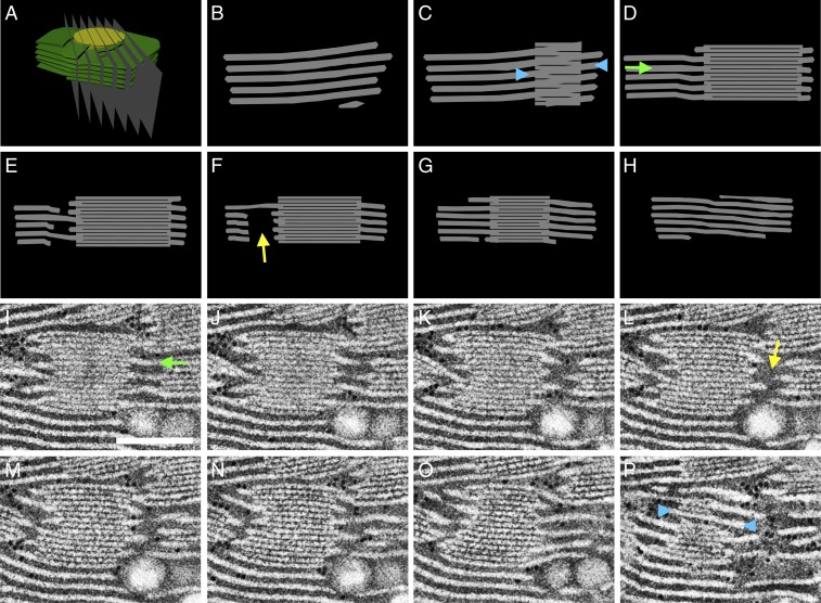
Fig. 8.
Cross-sections through the idealized model of the granum–stroma assembly accurately reproduce the tomographic data. (A) The idealized 3D model of a granum–stroma assembly, with a single left-handed helical junction (Fig. 7), is sliced by serial planes (B–H). The resulting cross-sections are consistent with serial slices from the tomograms. One such example, from the TEM data, encompassing a left-handed helical junction is presented in I–P. (Scale bar, 250 nm.) In both modeled and tomographic sections, discontinuities of the lamellar extensions (yellow arrows) are visible in slices traversing the central void of the helical connectors. Likewise, in both cases the stroma lamellae generally extend orthogonally (green arrows) to the grana stacks, aside from at the grana–stroma interface where they wrap the grana obliquely (blue arrowheads) to form right-handed helices. Note that in C and P the granum is viewed from the front and the back, respectively.

