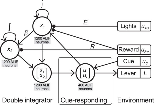
Figure 3.
Block diagram of the spiking neural implementation of the adaptive control network. Circles represent populations of adaptive leaky integrate-and-fire neurons. Left, The adaptive control model contains the double-integrator network from Singh and Eliasmith (2006). It has been modified by accepting both press information (u) and error information (E uTO) to drive x1, and reward information (R uRw) to control the integration of both x1 and x2. Lines terminating with circles indicate negative connections; lines terminating with arrowheads indicate positive connections. The output of the double integrator is the only component that interacts with the cue-responding network. Middle, The cue-responding network alone is able to perform the simple reaction-time task by responding to the Cue (uC) provided by the environment (see Materials and Methods, Cue-responding network). The influence of the double-integrator network allows the cue-responding network to respond adaptively based on the outcome of the previous trial. Right, Values that are not modeled with spiking neural populations, and are therefore considered signals that are provided by the environment. The lever is modified by the decoded output of the cue-responding network.

