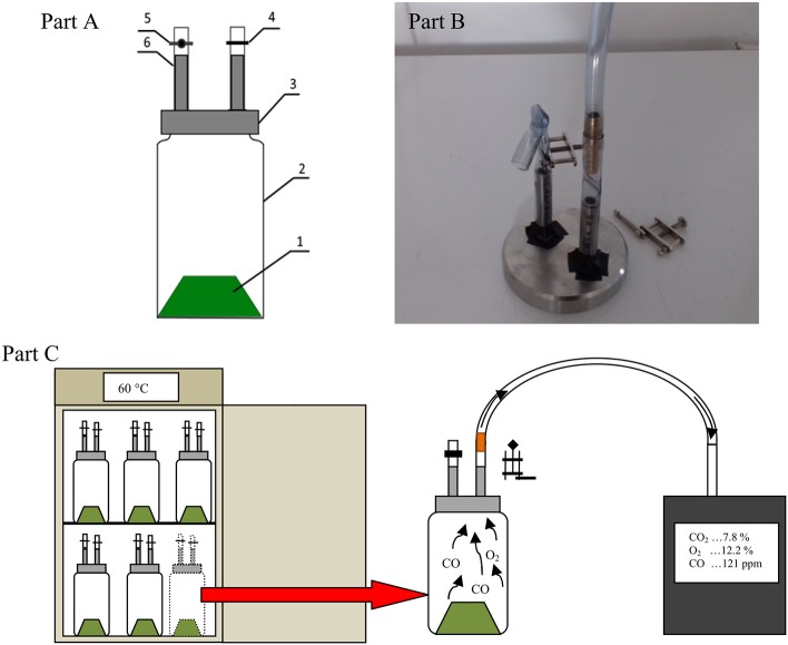
Figure 1.
Diagram of the gas production measuring vessel with connectors for gas sampling (A), Photo of connectors with the ignition wire (B), 1, digested material; 2, glass vessel; 3, connectors for gas sampling; 4, hose clamp; 5, Hoffman clamp; 6, silicon tube. Scheme of measuring gases in a reactors (C).

