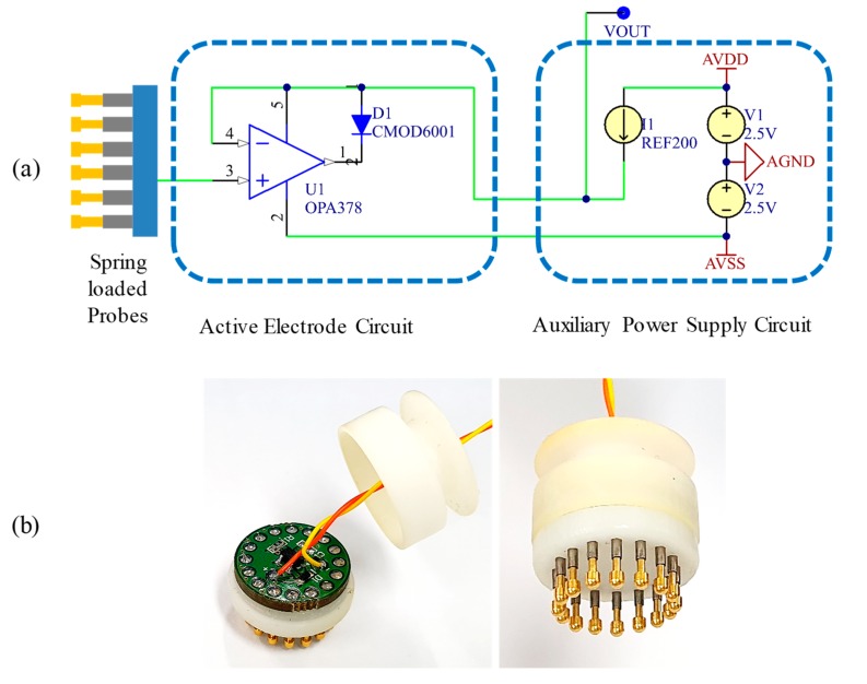
Figure 3.
Actual implemented schematic (a) and images (b) of the proposed active dry electrode. The proposed electrode system comprises the electrode unit itself and an auxiliary circuit board for the voltage and current power supplies. In the electrical schematic, decoupling capacitors for stabilized voltage supplies are omitted for simplicity.

