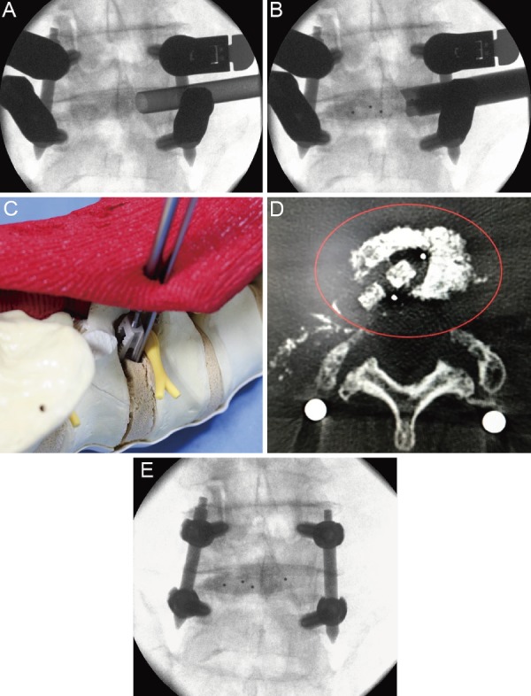
Figure 4.

A: The graft bone was introduced into the intervertebral space via the oval sleeve. B and C: The tip of the J-shaped nerve retractor was kept in the intervertebral disk space to prevent the exiting nerve root from straying into the cage entry path, and the cage was inserted along the J-shaped nerve retractor. D: The cage was positioned in the intervertebral space. E: The final task was compression between the vertebral bodies.
