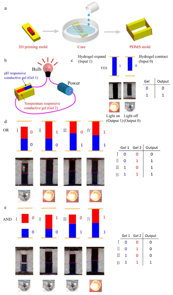
Figure 6.
The design of logic gates. Schemes illustrating (a) preparation of molds using polydimethylsiloxane (PDMS); (b) using power, a bulb, PDMS molds, and stimuli-responsive conductive hydrogels to form logic gates. The red rectangles represent temperature-responsive conductive hydrogels and the blue rectangles represent pH-responsive conductive hydrogels; (c) thedifferent states of the YES gates and the truth tables; (d) the different states of the AND gates and the truth tables; (e) the different states of the OR gates and the truth tables.

