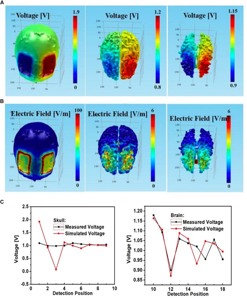
FIGURE 10.
Bilateral DLPFC montage with anode over the left DLPFC, cathode over the right DLPFC using rectangular pads as the stimulation electrodes; simulated (A) electric potential and (B) electric field in skull (left), gray matter (middle) and white matter (right); (C) simulated and measured voltages at the nine monitoring electrodes in the skull (left) and brain (right) layers.

