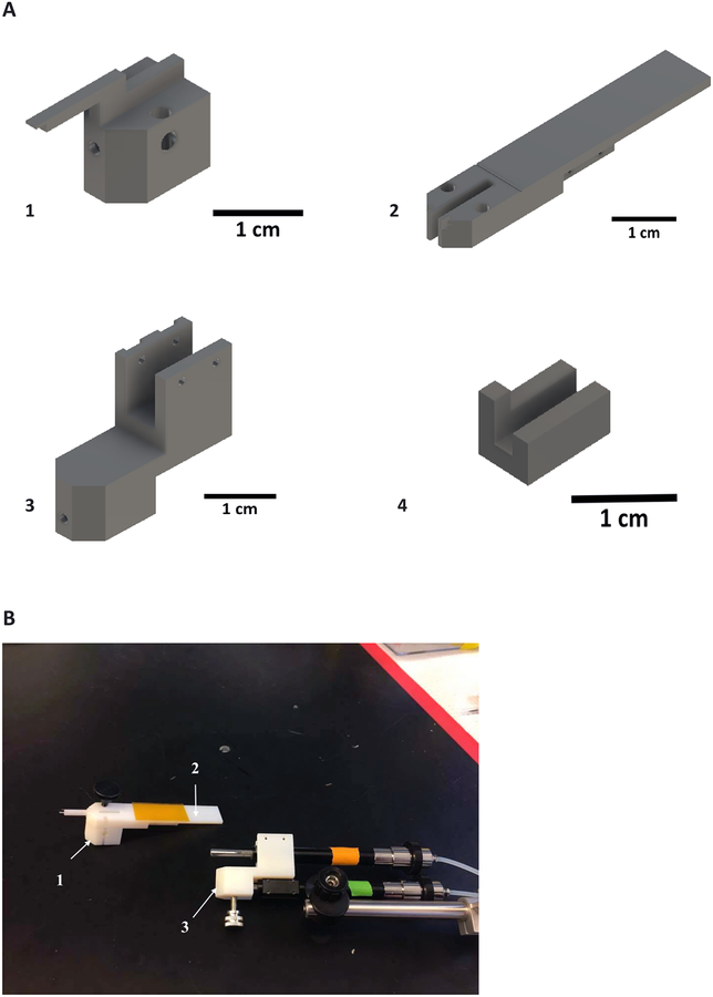
Figure 1: Inserter components.
(A) Pieces 1 and 2 are temporarily fixed to each other with a removable screw and will later be docked onto the retraction micromanipulator piston (orange). (B) The array and insertion shuttle are adhered to piece 1 and the array connector is attached to piece 2 with double-sided tape. Piece 3 connects the retraction micromanipulator and pieces 1 and 2 to the insertion micromanipulator (green). The insertion micromanipulator is fixed to a stereotactic adapter for implant positioning. Pieces 1–3 are pictured in their relative sizes. Piece 4 is a stabilizing piece for proper alignment of the insertion shuttle.

